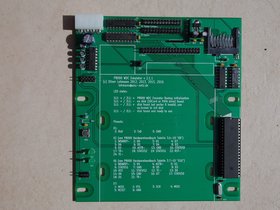
EAW P8000 WDC Emulator
|
2.x |
|
|
|
|
|
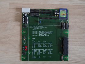
| v2 Prototype (2015) | v2 Prototype (2016) | v2.0 (2016) | v2.1 (2016) | v2.1.1 (2016) | |
|
1.x |
|
|
|
||
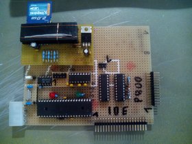
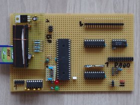
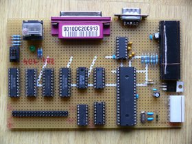
| v1 Prototype (2012) | v1.0 (2012) | v1.2 (2013) |
Features
- ATMega 1284P running at 18.4320MHz
- Data storage on
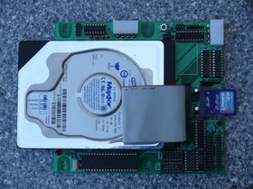
- SD-Card
- SDHC-Card
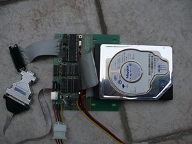
- PATA (IDE) hard disk
- compact dimensions
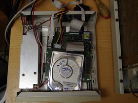
- fits in a 5.25" Slot in the P8000 Compact
- can be mounted easily in a 5.25" case for the P8000
- standard power connector (5.25" Molex plug)
Hardware Downloads
| Release Date | Version | Notes | PCB Layout | Circuit Diagram |
|---|---|---|---|---|
| 2016-06-22 | 2.1.1 |
|
||
| 2016-04-24 | 2.1 |
|
||
| 2016-03-15 | 2.0 |
|
||
| 2013-09-04 | 1.2 |
|
||
| 2012-06-27 | 1.0 |
|
- |
Software Downloads
| Release Date | Version | Notes | matching Board | Software |
|---|---|---|---|---|
| 2016-07-02 | 2.10 |
|
2.x | Github Release Page |
| 2016-03-15 | 2.00 |
|
tar.gz elf |
|
| 0.92 |
|
1.x | never released | |
| 2013-04-28 | 0.91 |
|
tar.gz elf |
Performance
This are the transfer rates I measured in WEGA. So the times are: P8000 16Bit accesses the Harddisk attached to the original WDC or the Emulator. I executed 10 or more runs of each method. The methods where:
- dd reading /dev/z with a blocksize of 4K and 3840 blocks (RAM-Disk only 768 blocks)
- dd reading /dev/rz with a blocksize of 4K and 3840 blocks (RAM-Disk only 768 blocks)
- dd reading a file in /z with a blocksize of 4K and 3840 blocks (RAM-Disk only 512 blocks)
- Bonnie which was compiled with the unsegmented WEGA system compiler cc with -O optimisation switch working with a 15MiB file (RAM-Disk only 2MiB file)
| P8000 WDC | Emu PATA | Emu SD-Card | ||||
|---|---|---|---|---|---|---|
| MR-535 | HH-1050 | ST251-1 | 3MiB RAM-Disk | |||
| bonnie write intelligently | 59.32 KiB/sec | 52.08 KiB/sec | 59.58 KiB/sec | 61.13 KiB/sec | 66.84 KiB/sec | 58.20 KiB/sec |
| bonnie read intelligently | 51.59 KiB/sec | 40.23 KiB/sec | 52.22 KiB/sec | 100.89 KiB/sec | 76.12 KiB/sec | 77.52 KiB/sec |
| dd /dev/z read | 58.34 KiB/sec | 59.22 KiB/sec | 59.65 KiB/sec | 128.00 KiB/sec | 99.48 KiB/sec | 100.91 KiB/sec |
| dd /dev/rz read | 113.69 KiB/sec | 82.58 KiB/sec | 91.98 KiB/sec | 132.35 KiB/sec | 224.11 KiB/sec | 179.89 KiB/sec |
| dd /z/testfile read | 47.16 KiB/sec | 39.07 KiB/sec | 47.78 KiB/sec | 93.09 KiB/sec | 73.25 KiB/sec | 74.53 KiB/sec |
The following transfer rates are direct accesses from the ATMega without any P8000 communication. The rates strongly depend on the PATA drive and more important on the SD-Card used! With some SD-Cards I experienced less then half of the transfer rates. While the Emulator runs at 18.432MHz for propper baud rate generation, I also tested the speed at 20 MHz.
| Multiblock (4096B) | Singleblock (512B) | |||
|---|---|---|---|---|
| 18.432 MHz | PATA | SD-Card | PATA | SD-Card |
| write | 1586 KiB/Sec | 546 KiB/Sec | 1413 KiB/Sec | 211 KiB/Sec |
| read | 1594 KiB/Sec | 537 KiB/Sec | 1490 KiB/Sec | 648 KiB/Sec |
| 20.000 MHz | PATA | SD-Card | PATA | SD-Card |
| write | 1683 KiB/Sec | 582 KiB/Sec | 1502 KiB/Sec | 216 KiB/Sec |
| read | 1722 KiB/Sec | 581 KiB/Sec | 1605 KiB/Sec | 673 KiB/Sec |
Story
In May 2012 I finally decided to build a replacement for the old P8000 WDC Controller. The P8000 WDC Controller is a Z80 system
interfacing with up to three ST506 hard disks. The WDC Controller communicates with the P8000 Computer via a Z80-PIO which is located
on the 16Bit-Board of the P8000 Computer. This PIO is dedicated to the communication with the WDC Controller. As usual, the
Z80-PIO is divided into two parts - the PIO-A and the PIO-B each one being able to serve 8 Bits of data.
In this implementation here, PIO-A serves as the data-input/output interface transporting the data blocks from the hard disk
as well as the so called "command codes". The PIO-A is programmed in mode 0 (output) and mode 1 (input) and is set to each mode
during run-time by the firmware of the Z8001. The PIO-B is used in mode 3 (control) and serves as a status information monitor.
Communication between Computer and Controller in detail
The signals
| Signal | Port | I/O at WDC |
Meaning |
|---|---|---|---|
| D0-D7 | PIO-A | I/O | 8Bit data received from and transmitted to the Z8001 |
| /RST | PIO-B | I | When active, the WDC will sleep and accept no commands |
| /ASTB | PIO-A | O | acknowledges the receipt of data from Port A, or tells the PIO to load data into Port A |
| /TR | PIO-B | O | Indicates towards the Z8001, that a transfer of data will happen |
| STATUS0-2 | PIO-B | O | Status Codes to indicate, that an error happened on processing the command or that everything went fine |
| /TE | PIO-B | I | Indicates, that a transfer of data towards the WDC is about to start |
| /ARDY | PIO-A but inverted | I | Indicates, that data can be read from the PIO-A, or data can be sent to the PIO-A |
Initialisation
Before any operation starts, the Z8001 will set the /Reset Signal to high which literally wakes up the WDC. As long
as /Reset remains high, the WDC will listen on the Z80-PIO Port A for receiving Command Codes telling the WDC what
to do next.
The Command Code
Every communication from the Z8001 to our WDC starts with a Command Code. Such a Command Code is a string length of nine bytes. The first byte
always indicates the action the WDC has to do. The following five bytes contain data that has to be interpreted depending on the
command code. Such data could be a block number to write on, a head/cylinder/sector to format or even a RAM address to store
or read data from. The seventh and eighth byte may also contain valid data for some commands. If they are used, they contain the length
of the data to receive from or transmit to the Z8001 after the Command Code arrival. The last, ninth byte is always 0xFF.
Receiving a Command Code
The transfer of the Command Code is only initiated by the Z8001. But the Z8001 will only send a command code when the WDC sets
the correct status from its 3 status lines (0x01 = get command). Every transfer will be then set up by the Z8001 by setting the /TE signal
to High. Basically, after /Reset went to High, the Emulator sets status 0x01 and then sits there and waits until /TE goes High.
When /TE goes high, this tells the Emulator that data will now arrive. After /TE has gone high, the Emulator then waits until the /ARDY
signal goes high as well.
Attention! The /ARDY signal of the WDC is the inverted ARDY signal of the Z80-PIO. So - when the /ARDY signal is high on the WDC, it is
low (not active) at the Z80-PIO.
After the /ARDY signal is high at the WDC (=Now data is written into the Z80-PIO by the Z8001) a loop is entered.
The loop now waits until the /ARDY signal goes to low (high at Z80-PIO) which indicates that data can now be read from the Z80-PIO.
At the same moment, the Emulator sets the /ASTB signal to low (=active) telling the Z80-PIO, that now the data transmission happens.
As soon as the data has been read by the WDC, the /ASTB signal is set to high to indicate the Z80-PIO, that the data transfer has been
finished. Now the WDC waits until /ARDY goes to high again which indicates, that the Z80-PIO realised, that the data was transferred.
The loop will now continue with waiting until /ARDY gets low again and so on. This happens nine times to receive all nine bytes of the
Command code.
Analysing of the Command Code
TODO description
Receiving Data
TODO description
Sending Data
TODO description
List of all Command Codes
All known codes are listed. Only the Command Codes used by any available Software where implemented. Some commands have a "Drive" parameter. It is checked, by the emulator that the specified "Drive" by the host does not exceed the number of attached drives. Since only 1 drive is attachable, the "Drive" number must always be 0.
| Code | Meaning | Byte 1 | Byte 2 | Byte 3 | Byte 4 | Byte 5 | Byte 6 | Byte 7 |
|---|---|---|---|---|---|---|---|---|
| 0x01 | read data beginning at given sector | Drive | Cylinder | Head | Sector | No. of bytes to be transfered | ||
| 0x02 | write sector | Drive | Cylinder | Head | Sector | No. of bytes to be transfered | ||
| 0x04 | format a track | not implemented | ||||||
| 0x08 | read data from WDC RAM | the RAM address | No. of bytes to be transfered | |||||
| 0x11 | read sector taking the Bad Track Table (BTT) into account | not implemented | ||||||
| 0x12 | write sector taking the BTT into account | not implemented | ||||||
| 0x14 | format and reread a track | Drive | Cylinder | Head | Sector | |||
| 0x18 | write data to WDC RAM | the RAM address | No. of bytes to be transfered | |||||
| 0x21 | read data beginning at given block | Drive | the disk block number | No. of bytes to be transfered | ||||
| 0x22 | write data beginning at given block | Drive | the disk block number | No. of bytes to be transfered | ||||
| 0x24 | format a track and provide BTT info | Drive | Cylinder | Head | Sector | |||
| 0x28 | read parameter block from WDC RAM | No. of bytes to be transfered | ||||||
| 0x38 | read error statistics | No. of bytes to be transfered | ||||||
| 0x44 | verify track | Drive | Cylinder | Head | Sector | |||
| 0x48 | delete BTT from WDC RAM | no additional parameters | ||||||
| 0x58 | read BTT from WDC RAM | No. of bytes to be transfered | ||||||
| 0x68 | write BTT to WDC RAM | No. of bytes to be transfered | ||||||
| 0x78 | write parameter block to WDC RAM | No. of bytes to be transfered | ||||||
| 0x81 | verify sector | not implemented | ||||||
| 0x82 | write and re-read sector | not implemented | ||||||
| 0x84 | delete a track | not implemented | ||||||
| 0x92 | write and re-read sector taking BTT into account | not implemented | ||||||
| 0xa1 | copy block from drive 1 to drive 0 | not implemented | ||||||
| 0xa2 | write and re-read block | not implemented | ||||||
| 0xc2 | store parameter block and BTT on the harddisk | no additional parameters | ||||||
Command Code Usage:
| Source Code | 0x01 | 0x02 | 0x04 | 0x08 | 0x11 | 0x12 | 0x14 | 0x18 | 0x21 | 0x22 | 0x24 | 0x28 | 0x38 | 0x44 | 0x48 | 0x58 | 0x68 | 0x78 | 0x81 | 0x82 | 0x84 | 0x92 | 0xa1 | 0xa2 | 0xc2 |
| firmware/MON16/p.disk.s | X | X | X | X | |||||||||||||||||||||
| WEGA/src/cmd/standalone/sa.diags/sa.test.s | X | X | X | X | |||||||||||||||||||||
| WEGA/src/cmd/standalone/sa.format.c | X | X | X | X | X | X | X | X | X | ||||||||||||||||
| WEGA/src/cmd/standalone/sa.shipdisk.c | X | X | |||||||||||||||||||||||
| WEGA/src/cmd/standalone/sa.verify.c | X | X | X | X | |||||||||||||||||||||
| WEGA/src/uts/dev/disk.s | X | X |
Open topics
- Check if BTT handling could or should be implemented. Right now, the BTT is ignored by all accesses
- Check how the error report in sa.format (key "t" at the last question) looks with the original WDC and how it looks with the emulator
Original WDC - formating CHS 81/0/0 - 81/8/17
Total Errors since RESET: 42106---> 55330 * 'A'/30076 * 'B'/13175 * 'C'/48051 * '10'/41851 * '11'/50231 * '12'
Emulator - formatting CHS 145/0/0 - 145/4/16
Total Errors since RESET: 14202---> 32968 * 'A'/23583 * 'B'/6972 * 'C'/64069 * '10'/16400 * '11'/1282 * '12'
- Check how the output of the timing constants behaves in sa.format
Original WDC
PAR --- z40: 203 z41: 209 zmin40: 251 zmax40: 253 zmin41: 241 zmax41: 243
Emulator
PAR --- z40: 0 z41: 0 zmin40: 0 zmax40: 0 zmin41: 0 zmax41: 0